Chapter 7 Systems Of Particles And Rotational Motion
CHAPTER NO.7 SYSTEMS OF PARTICLES AND
ROTATIONAL MOTION
7.1 INTRODUCTION
In the earlier chaptera we primarily considered the
motion ofa single particle. (A particle is represented as a point mass.It has
practically no size.) We applied the resulta of our
study even to the motion of bodies of finite size,
assuming that motion of such bodies can be described in terms of the motion of
a particle.
Any real body which we encounter in daily life has a
finite size. In dealing with the motion of extended bodies
(bodies of finite size) often the idealised model of
a particle is
fnadequate. In thia chapter we shall try to go
beyond this tnadequacy. We shall attempt to bufld an understanding of
the motton of extended bodies. An extended body, in
the firat place, ia a system of particles. We shall begin with the
consideration of motion of the syatem as a whole. The centre of mass of a
system of particles will be a key concept here.We shall discuss the motion of
the centre of masa of a system
of particles and usefulness of this concept in
understanding the motion of extended bodies.
A large class of problema with extended bodies can
be solved by considering them to be rigid bodies. Ideally a rigid bady is a
body with a perfectly definite and
unchanging shape. The distances between all pairs of
particles of such a body do not change. It is evident from
thia definition of a rigid body that no real body ts
truly rigid,since real bodies deform under the influence of forces. But in many
situations the deformations are negligible. Ina number
of situations involving bodiea such as wheels, tops,
ateel ‘beams, molecules and planets on the other hand, we can ignore that they
warp, bend or vibrate and treat them as rigid.7.1.1 What kind of motion can a
rigid body have?
Let us try to explore this question by taking some
examples of the motion of rigid bodies. Let us begin with a rectangular block
sliding down an inclined plane without any sidewise
movement. The block is a rigid body. Its motion down
the plane is such that all the particles of the body are moving together, 1.c.
they have the
same velocity at any instant of time. The rigid body
here is in pure translational motion (Fig. 7.1).
In pure translational motion at any instant of time all particles of the body have the same velocity.
Consider now the rolling motion of a solid metallic or wooden cylinder down the same inclined plane (Fig. 7.2). The rigid body in this problem, namely the cylinder, shifts from the top to the bottom of the inclined plane, and thus,
has translational motion. But as Fig, 7.2 shows,all
its particles are not moving with the same velocity at any instant. The body
therefore, is
not in pure translation. Its motion is translation
plus ‘something elze.’
In order to understand what this ‘something else’
is, let us take a rigid body ao constrained that it cannot have translational
motion. The most common way to constrain a rigid body so that ft doca not have
translational motion is to
fix it along a straight line. The only possible mnotion
of such a rigid body is rotation. The line along which the body ts fhoed is
termed as its axis of rotation. If you look around, you
will come across many examples of rotation about an
axis, a cedling fan, a potter's wheel, a giant wheel in a fair, a merry-go-round
and so on (Fig 7.3(a) and (b)).

Let us try to understand what rotation is,what
characterises rotation. You may notice that in rotation of a rigid body about a
fixed axis, every particle of the body moves in a circle, which lies in a plane
perpendicnolar to the axis and has its centre on the axis. Fig.
7.4 shows the rotational motion of a rigid body
about a fixed axis (the z-axis of the frame of reference}. Let P, be a particle
of the rigid body,
arbitrarily chosen and at a distance r, from fixed
axia. The particle P, describes a circle of radius
7, with its centre C, on the fixed axis. The circle
lies in a plane perpendicular to the axis. The figure also shows another
particle P, of the rigid
body, P, is at a distance r, from the fixed axis.The
particle P, moves in a circle of radius rand with centre C, on the axis. This
circle, too, Hes
in a plane perpendicular to the axis. Note that the
circles described by P, and P, may He in different planes; both these planes,
however,are perpendicular to the fixed axis. For any particle on the axis like
P,, r = 0. Any such
particle remains stationary while the body rotates.
This is expected since the axis is fixed.

In some examplea of rotation, however, the axis may
not be fixed. A prominent example of this kind of rotation is a top spinning in
place [Fig. 7.5{a)]. (We assume that the top does not.slip from place to place
and so doea not have
translational motion.) We know from experience that
the axia of such a spinning top moves around the vertical through its point of
contact.with the ground, sweeping out a cone as shown
in Fig. 7.5{a). (This movement of the axis of the
top around the vertical ia termed precession.)Note, the point of contact of the
top with ground is fixed. The axis of rotation of the top
at any instant passes through the point of contact.
Another simple exampk of this kind of rotation is the oscillating table fan or
a pedestal fan. You may have observed that the axis of
rotation of such a fan has an oscillating (sidewise)
movement in a horizontal plane about the vertical through the point at which
the axis
is pivoted (point O in Fig. 7.5(b)).
While the fan rotates and its axis moves
sidewise, this point is fixed. Thus, in more general
cases of rotation, such as the rotation of a top or a pedestal fan, one point
and not one line, of the rigid body is fixed. In this case the axis is not
fixed, though it always passes
through the fixed point. In our study, however,‘we
mostly deal with the simpler and special case of rotation in which one line
(Le. the axis) is Fg 7.6 (a} and 7.6 (b) Mustrate different motions of the same
body. Note P ts an arbitrary potul of the bedy; O ts the centre of mass of the
body, which is defined in the next section. Suffice to say here that the
trajectories of O are the translational trajectories Tr, and Tr, of the body.
The posttions O and P at
twee different instants of time are shown by O,,
O,,and O,, and P,, P, and P,, respectively, in both gs. 7.6 fa} and (b) . As
seen from Fig. 7.6ia), at any tnstant the velocities of any particles ice O and
P of the body are the same in pure translation. Notice, in
tits case the orientation of OP, Le. the angle OP
makes with a fixed direction, say the horizontal, remains the same, Le. a, = a,
= a, Fig. 7.6 (b} tlusirates a case of combination of translation and rotation.
In this case, at any instants the velocities of O and P differ. Also, a,, a,
and a, may all be different.
fixed. Thus, for us rotation will be about a fixed
axis only unless stated otherwise.

The rolling motion of a cylinder down an
inclined plane is a combination of rotation about a
fixed axis and translation. Thus, the ‘something else’ in the case of rolling
motion
which we referred to earlier is rotational
motion.You will find Fig. 7.6(a) and (b) instructive from
this point of view. Both these figures show motion
of the same body along identical translational trajectory. In one case, Fig.
7.6(a),the motion is a pure translation; in the other
case [Fig. 7.6(b)] it is a combination of
translation and rotation. (You may try to reproduce the two types of motion
shown using a rigid object like a heavy book.)
We now recapitulate the most important
observations of the present section: The motion of a
rigid body which is not pivoted or fixed in some way is either a pure
translation or a combination of translation and rotation. The
motion of a rigid body which is pivoted or fired in
some way is rotation. The rotation may be about an axis that is fixed (e.g. a
ceiling fan) or moving (e.g. an oscillating table fan). We
shall, in the present chapter, consider rotational
motion about a fixed axis only.
7.2 CENTRE OF MASS
‘We shall first see what the centre of mass of a
system of particles is and then discuss its significance. For simplicity we
shall start with
a two particle system. We shall take the line joiing
the two particles to be the x- axis.
Let the distances of the two particles be x,and x,
respectively from some origin 0. Let m,and m, be respectively the masses of the
two particles. The centre of mass of the system is
that point C which fs at a distance X from O,
where X is given by
MX, FIMX;
X= 11 es
m, +m, (7.1)
In Eq. (7.1), Xcan be regarded as the maas-weighted
mean of x, and x,. If the two particles have the same maaa m, = m, = m then
xe MY, FM, _ +X,
2m 2
Thus, for two particles of equal mass the centre of
mass lies exactly midway between them.
If we have n particles of masses m,, m,,
...m, respectively, along a straight line taken as
the x- axis, then by definition the position of the centre of the maas of the
system of particles
is given by
xe FMA te AMX yx,
M, +My +....4M, ym.
(7.2)
where X,, X,,...x, are the distances of the
particles from the origin; X is alao measured from the same origin. The symbol
> (the Greek letter sigma) denotes summation, in this case
over n particles. The sum
yn =M
is the total mass of the system.
Suppose that we have three particles, not lying in a
straight line. We may define x and y-axes in the plane in which the particles
lie and represent the positions of the three particles by
coordinates O¢,.y,), (x,y) and bc,.¥,)
respectively.Let the masses of the three particles be m,, ™ and m,
respectively. The centre of mass C o the system of the three particles is
defined and located by the coordinates (X. Y) given by
, MX, HAMAX, FMX,
X= yl ere Je3
Mm, FM, +M; (7.3a)
, MY, FOU, FOLLY,
Y = 1SA1 2efs JSf3
Mm +My, #M; (7.30)
For the particles of equal mass m= m, =m,
= My.
Xe MX, Xo FXy) OX AX + Xy
- 3m - 3
7 3m - 3
Thus, for three particles of equal mass, the centre
of mass coincides with the centroid of the triangle formed by the particles.
Results of Eqs. (7.3a} and (7.3b) are
generalized easily to a system of n particles, not
necessarily lying in a plane, but distributed in pace. The centre of mass of
such a system is
at (X, Y, Z), where
, Ymrx,
Xa
M (74a)
ye ee
M (7.4b)
gee
and M (7.4c)
Here M = yn, is the total mass of the
system. The index iruns from | to n; m, is the mass
of the @ particle and the position of the & particle is given by (x, y,,
Z).
Eqs. (7.4a), (7.4b) and (7.4c) can be
combined into one equation using the notation of
position vectors. Let r, be the position vector of the ¢ particle and R be the
position vector of
the centre of mass:
r=x,i+y, j+z,k
and R=Xi+y j+Zk
Then R= 2% (7.40)
M
The sum on the right hand side is a vector sum.
Note the economy of expressions we achieve by use of
vectors. If the origin of the frame of reference (the coordinate system) is
chosen to
be the centre of mass then Ym, = 0 for the given
system of particles.
A rigid body, such as a metre stick or a
flywheel, is a system of closely packed
particles;Eqs. (7.4a), (7.4b), (7.4c) and (7.4d) are therefore, applicable to a
rigid body. The number of particles (atoms or molecules) in such a body
is so large that it is impossible to carry out the
summations over individual particles in these equations. Since the spacing of
the particles is small, we can treat the body as a continuous
distribution of mass. We subdivide the body into
nsmall elements of mass; Am,, Am... Am,; the f element Amis taken to be located
about the point (x, ¥, Z). The coordinates of the centre of
mass are then approxhnately given by
7 Yam x, Ylanu, Yam, )z,
xX =" yea Zao
yAm, yam, yam,
As we make n bigger and bigger and each
Am, smaller and smaller, these expressions become exact. In that case, we
denote the stums over i by integrals. Thus,yam, > Jam =M,
Yam, > fxam.
Tiampy, 3 Juam,
and Tam, )Z, 9 Jz dm
Here M is the tota] mass of the body. The
coordinates of the centre of mass now are X= a xdm Y= = Jydm and z-—f zdm
(7.5a)
The vector expression equivalent to these three
scalar expressions is
1
R=>,Jrdm (7.5b)
If we choose, the centre of mass as the origin of
our coordinate system,
R=0
Le., jrdm =0
or fxdm =Jydm= [zdm=o (7.8)
Often we have to calculate the centre of mass of
homogeneous bodies of regular shapes like rings, discs, spheres, rods etc. (By
a homogeneous body we mean a body with uniformly distributed mass.) By using
symmetry consideration, we can easily show that the centres of mass of these
bodies lie at their geometric centres.
dm din
x-axis
x x
Fig. 7.8 Determining the CM of a thin rod.
Let us consider a thin rod, whose width and breath
(in case the cross section of the rod is rectangular) or radius (in case the
cross section of the rod is cylindrical) is much smaller than
its length. Taking the origin to be at the geometric
centre of the rod and x-axis to be along the length of the rod, we can say that
on account of reflection symmetry, for every element dm of the rod at x, there
is an element of the same mass din located at —x (Fig. 7.8).
The net contribution of every such pair to the
integral and hence the integral | xm itself is zero. From Eq. (7.6), the point
for which the integral itself is zero, is the centre of mass.Thus, the centre
of mass of a homogenous thin
rod coincides with its geometric centre. This can.be
understood on the basis of reflection symmetry.
The same symmetry argument will apply to
homogeneous rings, discs, spheres, or even thick
rods of circular or rectangular cross section. For all such bodies you will
realise that for every element dm at a point (x y, 2) one can
always take an element of the same mass at the point
(=x, -y, -2). (In other words, the origin is a point of reflection symmetry for
these
bodies.) As a result, the integrals in Eq. {7.5
a)all are zero. This means that for all the above bodies, their centre of mass
coincides with their geometric centre.
Example 7.1 Find the centre of mass of
three particles at the vertices of an
equilateral triangle. The masses of the
particles are 100g. 150g. and 200g
respectively. Each side of the equilateral triangle
is 0.5m long.

With the x-and y-axes chosen as shown in Fig.7.9,
the coordinates of points O, Aand B forming the equilateral triangle are
respectively (0,0),(0.5,0), (0.25,0.25./3). Let the masses 100 g,
150g and 200g be located at O, A and B be
respectively. Then,
x _ YX, FM, Mg Xy
“my, +m, +m;
[100 (0) + 150(0.5) + 200(0.25)] gm
~ (100 +150 + 200) g
_75+50, 1255
=—— m= ——m=—m
450 450 18
y [100(0) + 150(0) + 200(0.25¥3)} gm
~ 450 g
_ 50V3 3), = a
450 9 3¥3
The centre of mass C is shown in the figure.Note
that ft is not the geometric centre of the triangle OAB. Why? <
Example 7.2 Find the centre of mass ofa
triangular lamina.Arnssaver The lamina (ALMN) may be
subdivided into narrow atrips each parallel to the base (MN)
as shown in Fig. 7.10

By symmetry each strip has ita centre of
maaa at its midpoint. If we join the midpoint of all
the strips we get the median LP. The centre of maas of the triangle as a whole
therefore,
has to lie on the median LP. Similarly, we can argue
that it lies on the median MQ and NR.This means the centre of maas lies on the
point of concurrence of the medians, i.e. on the centroid G of the triangle.
<
Example 7.3 Find the centre of mass ofa
uniform L-shaped lamina (a thin flat plate}with
dimensions as shown. The mass of the lamina is 3 kg.
Answer Choosing the X and Yaxes as shown in Fig.
7.11 we have the coordinates of the vertices of the L-shaped lamina as given in
the figure. We can think of the
L-shape to consist of 3 squares each of length lm.
The mass of each square is 1kg, since the lamina is uniform. The centres of
mass C,, C,and C, of the squares are, by symmetry, their
geometric centres and have coordinates
(1/2,1/2),(3/2,1/2), (1/2,3/2) respectively. We take the masses of the squares
to be concentrated at
these points. The centre of mass of the whole L
shape (X, Y) is the centre of mass of these mass points.
Hence
x [1(1/2)+1(3/2)+10/2)|kgm 5
~ (+1+1kg -—
[[11/2)+10/2)+1(3/2)| |kgm 5
Y 5 > = -—m
(1+ 1+1)kg 6
The centre of mass of the L-shape lies on the line
OD. We could have guessed this without cakulations. Can you tell why? Suppose,
the three squares that make up the L shaped lamina of Fig. 7.11 had different
masses. How will you
then determine the centre of mass of the
lamina?
7.3 MOTION OF CENTRE OF MASS
Equipped with the definition of the centre of mass,
we are now in a position to discuss its physical importance for a system of
particles.We may rewrite Eq.(7.4d) as
MR= Ym, =Snyr tr, +..4m0, (7.7
Differentiating the two sides of the equation with
respect to time we get
|, dR dr, dr, dr,
Ma= mat Mage AME
or
“MV= my, 4mv, +...+,v, (7.8)
where v, (= dr, /dt) is the velocity of the first
particle Ve {=adr,/dt)is the velocity of the second particle etc. and V = dR/di
is the velocity of the centre of mass. Note that we assumed the masses m,. m,,
... etc. do not change in time. We have therefore, treated them
as constants in differentiating the equations with
respect to time.
Differentiating Eq.(7.8) with respect to time,‘We
obtain
uv _ mM, aw, mM, on +7, on
dt dt dt dt
or
‘MA =ma,+m,a,+..+m,a, (7.9)
where a, (= ctv, /dt) 1s the acceleration of the
first particle, ‘as (=dv, /dt) is the acceleration of the second particle etc. and
A(= dv /dt) is
the acceleration of the centre of mass of the system
of particles.
Now, from Newton's second law, the force
acting on the first particle is given by F,
=m_a,.The force acting on the second particle is given by F, =m.,a, and so on.
Eq. (7.9) may be written
aa
MA=F,+F, +...+F, (7.10)
Thus, the total mass of a system of particles times
the acceleration of its centre of masa is the vector sum of all the forces
acting on the system of particles.
Note when we talk of the force F, on the first
particle, ft ig net a single force, but the vector sum of all the forces on the
first particle; likewise
for the secomd particle etc. Among these forces on
each particle there will be external forces exerted by bodies outside the
system and also internal forces exerted by the particles on one
another. We know from Newton’s third law that these
internal forces occur in equal and opposite paire and in the sum of forces of
Eq. (7.10),their contribution is zero. Only the external
forces contribute to the equation. We can then
rewrite Eq. (7.10) as
MA=F.., (7.11)
where F.., represents the sum of all external forces
acting on the particles of the system.
Eq. {7.11} states that the centre of masa of a
system of particles moves as if all the mass of the system was concentrated at
the centre of mass and all the external farces were applied at that point.
Notice, to determine the motion of the centre of
mass no knowledge of tnternal forces of the system of particles is required;
for this purpose we need to know only the external forces.To obtain Eq. (7.11)
we did not need to specify the nature of the system of particles.
The system may be a collection of particles in which
there may be all kinds of internal motions, or it may be a rigid bedy which has
either pure translational motion or a combination of translational and
rotational motion. Whatever is the aystem and the motion
of {ts individual particles, the centre of mass
movea according to Eq. (7.11).
Instead of treating extended bodies as single
particles as we have done in earlier chapters,we can now treat them as systems
of particlea.We can obtain the translational component of their motion, i.e.
the motion centre of maas of the system, by taking the mass of the whole system
to be concentrated at the centre of mass and all the external forces on the
system to be acting at the centre of masa.
This fa the procedure that we followed earlier in
analysing forces on bodies and solving problems without explicitly outlining
and justifying the procedure. We now realise that in earlier studies we
assumed, without saying so,that rotational motion and/or internal motion
of the particles were either absent or negligible.We
no longer need to do this. We have not only found the justification of the
procedure we followed earlier; but we also have found how to describe and
separate the translational motion
of (1) a rigid body which may be rotating as well,
or (2) a system of particles with all kinds of internal motion.

Figure 7.12 is a good illustration of Eq. (7.11). A
projectile, following the usual parabolic trajectory, explodes into fragments
midway in air. The forces leading to the explosion are internal forces. They
contribute nothing to the
motion of the centre of mass. The total external
force, namely, the force of gravity acting on the body, is the same before and
after the explosion.The centre of mass under the influence of the external
force continues, therefore, along the same parabolic trajectory as it would
have followed if there were no explosion.
7.4 LINEAR MOMENTUM OF A SYSTEM OF
PARTICLES
Let us recall that the linear momentum of a particle
is defined as
‘p=amv (7.12)
Let us also recall that Newton's second law written
in symbolic form for a single particle is
dp
F di (7.13)
where F is the force on the particle. Let us
consider a system of n particles with masses m,, M,,...m, respectively and
velocities V,.V.,.......¥,, Respectively. The particles may be
interacting and have external forces acting on them.
The linear momentum of the first particle is m,v,, of the second particle is
m.v. and so on.
For the system of n particles, the linear Momentum
of the system is defined to be the vector sum of all individual particles of
the system,
P=p, +p, +...+P,
SMV, +M,V, +...4M,¥, (7.14)
Comparing this with Eq. (7.8)
‘P=MV (7.15)
Thus, the total momentum of a system
of particles is equal to the product of the total
mass of the system and the velocity of ita centre of mass. Differentiating Eq.
(7.15)with respect to time,
‘dP y.dv
—=M——=MA
dt dt (7-16)
Comparing Eq.(7.16) and Eq. (7.11),
P
=F. (7.17)
This is the statement of Newton's second
law extended to a system of particles.
Suppose now, that the sum of external
forces acting on a system of particles is zero.Then
from Eq.(7.17)
‘dP
*=0 or P =Constant (7.18a)
Thus, when the total external force acting on a
system of particles is zero, the total linear momentum of the system is
constant. This is the law of conservation of the total linear momentum of a
system of particles. Because of Eq. (7.15), this also means that when the total
external force on the system is zero the velocity of the centre of mass remains
constant. (We assume throughout the discussion on systema of particles in this
chapter that the total mass of the system
remains conatant.)
Note that on account of the internal forces,i.e. the
forces exerted by the particles on one another, the individual particles may
have complicated trajectories. Yet, if the total external
force acting on the system is zero, the centre of
mass moves with aconstant velocity, i.c., moves uniformly in a straight line
like a free particle.
The vector Eq. (7.18a) is equivalent to three scalar
equations,
P_=¢,P,=¢ and P,=¢, (7.18 b)
Here P,, P, and P, are the components of
the total near momentum vector P along the % y and 2
axea respectively; ¢,, ¢, and «, are constants.

As an example, let us consider the
radioactive decay of a moving unstable particle,like
the nucleus of radium. A radium nucleus disintegrates into a nucleus of radon
and an alpha particle. The forces leading to the decay
are internal to the system and the external forces
on the system are negligible. So the total linear momentum of the system is the
same before and after decay. The two particles produced in the decay, the radon
nucleus and
the alpha particle, move in different directions in
such a way that their centre of mass moves along the same path along which the
original decaying radium nucleus was moving Fig. 7.13(a)].
If we observe the decay from the frame of reference
in which the centre of mass is at rest,the motion of the particles involved in
the decay looks particularly simple; the product particles move back to back
with their centre of mass
remaining at rest as shown in Fig.7.13 {b).In many
problems on the system of
particles as in the above radioactive decay problem,
it is convenient to work in the centre of mass frame rather than in the
laboratory frame of reference.
In astronomy, binary (double) stars is a
common occurrence. If there are no external forces,
the centre of mass of a double star moves like a free particle, as shown in
Fig.7.14 (a). The trajectories of the two stars of equal
mass are also shown in the figure; they look
complicated. If we go to the centre of mass frame, then we find that there the
two stars are moving in a circle, about the centre of masa, which fs at rest.
Note that the position of the stars have to be diametrically opposite
to each other [Fig. 7.14(b)]. Thus in our frame of
reference, the trajectories of the stars are a combination of () uniform motion
in a straight line of the centre of mass and (ii) circular orbits of the stars
about the centre of masa.
As can be seen from the two examples,
separating the motion of different parts of a system
into motion of the centre of mass and motion about the centre of mase ts a very
useful technique that helps in understanding the motion of the system.
7.8 VECTOR PRODUCT OF TWO VECTORS
We are already familiar with vectors and their use
in physics. In chapter 6 (Work, Energy,Power) we defined the scalar product of
two vectors. An important physical quantity, work,
is defined as a scalar product of two vector
quantities, force and displacement.We shall now define another product of two
vectors. This product is a vector. Two important quantities in the study of
rotational motion,namely, moment of a force and angular momentum, are defined
as vector products.Definition of Vector
Product
A vector product of two vectors a and b is a vector
¢ such that magnitude ofe =c = ahsing where a and b are magnitudes of a and b
and 4 is the angle between the two vectors.
(i) is perpendicular to the plane containing a and
b.
(ii ifwe take a right handed screw with ite head
lying in the plane of a and b and the screw perpendicular to this plane, and if
we turn the head in the direction from a to b, then the tip of the screw
advances in the direction
of sc. This right handed screw rule is
Mlustrated in Fig. 7.15a.
Alternately, if one curls up the fingers of right
hand around a line perpendicular to the plane of the vectors a and b and if the
fingers
are curled up in the direction from a to b, then the
stretched thumb points in the direction of as shown in Fig. 7.15b.

A simpler version of the right hand rule is the
following : Open up your right hand paln and curl the fingers pointing from a
to b. Your stretched thumb points in the direction of e.
It should be remembered that there are two angles
between any two vectors a and b. In Fig. 7.15 (a) or (b) they correspond to 0
(as shown) and (360°- §. While applying either of the above rules, the rotation
should be taken
through the smaller angle (<180°) between a and
b. It is 6 here.
Because of the cross used to denote the
vector product, it is also referred to as cross
product.Note that scalar product of two vectors is commutative as said earlier,
a.b = ba
The vector product, however, is not
commutative, ie.axbzbxa The magnitude of both a x b
and b x a is the same (absing); also, both of them are
Perpendicular to the plane of a and b. But the
rotation of the right-handed screw in case of axhb ie from atob, whereas in
case of bx a it is from b to a. This means the two vectors are
in opposite directions. We have
axb=-bxa
Another interesting property of a vector
product is its behaviour under reflection.Under
reflection (le. on taking the mirror image) we have x >-—x.y -yamdz—4-z.As a
result all the components of a vector change sign and thus a@—>-a. bo-b.What
happens to a x b under reflection?
a x b— (-a)x(-b) =axb
Thus, a x b does not change sign under
reflection.Both scalar and vector products are distributive
with respect to vector addition.Thus,
a(b+c)=abtac
ax(b+c)=axb+axc
We may write c = a x b in the component
form. For this we first need to obtain some
elementary cross products:
ax a=0 (0 is a null vector, i.e. a vector with zero
magnitude)
This follows since magnitude ofa x a is
a* sin0®=0-
From this follow the results
ixi=0. jxj=0. kxk=0
i) ixj-k
Note that the magnitude of i x j is sin90°or 1,
since j and j both have unit
magnitude and the angle between them is 90°.Thus, ix
j is a unit vector. A unit vector perpendicular to the plane of ; and j and
Telated to them by the right hand screw rule is ‘- Hence, the above result. You
may verify similarly,
jxk=i and kxi=j From the rule for commutation of the
cross product, it followa:jxie-& &xje-i ixk--j
Note if i,j. koccur cyclically in the above vector
product relation, the vector product is positive. If i.j.k do not occur in
cyclic order,the vector product is negative.
Now,
axb=(a,i+ a,j + ak) x(b.i+ b,j + bk)
= a,b, k -a,b,j- a,b. + a,b,i +a,bj- a,b,i
= (a,b, — a,b, ji+ (a,b, —a,b,)j+ (a,b, - a,b Jk
We have used the elementary cross products in
obtaining the above relation. The expression fora xb can be put in a
determinant form which is easy to remember.
. ij t
axb=la, a, a,
b, by b,
Example 7.4 Find the scalar and vector
products of two vectors. a = (31 - 44 + 5k)and b =
(- 21+ j- 3k)
Answer
‘arb = (3i— 4j + Ske)o(-2i+ j- 3k)
=-6-4-15
=-25
. ij k
axb=|3 -4 5|=7i-j-5k
—2 1 -3
Note bxa=-7i+j+5k <
7.6 ANGULAR VELOCITY AND ITS RELATION
WITH LINEAR VELOCITY
In this section we shall study what is angular
velocity and its role in rotational motion. We have seen that every particle of
a rotating body
moves in a circle. The linear velocity of the
particle is related to the angular velocity. The Telation between these two
quantities involves a vector product which we learnt about in the
last section.
Let us go back to Fig. 7.4. As said above, in rotational motion of a rigid body about a fixed axis, every particle of the body moves in a circle,

which lies in a plane perpendicular to the axis
and has its centre on the axis. In Fig. 7.16 we
redraw Fig. 7.4, showing a typical particle {at a point P) of the rigid body
rotating about a fixed
axis (taken as the z-axis). The particle describes a
circle with a centre C on the axis. The radius of the circle is r, the
perpendicular distance of the point P from the axis. We also show the
linear velocity vector v of the particle at P. It ts
along the tangent at P to the circle.
Let P’ be the position of the particle after an
interval of time At (Fig. 7.16). The angle PCP’describes the angular
displacement Aé@ of the
partick: in time At. The average angular velocity of
the particle over the interval Af is A@/At. As At tends to zero {i.e. takes
smaller and smaller
values), the ratio A6/Atapproaches a limit which is
the instantancous angular velocity d6/dt of the particle at the position P. We
denote the instantancous angular velocity by (the Greek letter omega}. We know
from our study of circular motion that the magnitude of linear velocity v of a
particle moving in a circle is related to the angular velocity of the particle
o by the simple relation v=@r, where r ts the radius of the circle.
We observe that at any given instant the
relation C= ©r applies to all particles of the Tigid
body. Thus for a particle at a perpendicular distance r, from the fixed axis,
the linear velocity
at a given instant v, is given by
vo =or, (7.19)
The index {runs from 1 ton, where nis the total
number of particles of the body.
For particles on the axis, y = 0. and hence v= o@r=
0. Thus, particles on the axis are stationary. This verifics that the axis is
fixed.
Note that we use the same angular velocity for all
the particles. We therefore, refer to o as the angular velocity of the whole
body.
We have characterised pure translation of a body by
all parts of the body having the same velocity at any instant of time.
Simflarly, we may characterise pure rotation by all parts of ths body having
the sams angular velocity at any inatant of time. Note that this
characterisation of the rotation of a rigid body
about a fied axis is just another way of saying as in Sec. 7.1 that each
particle of the body moves
in a circle, which Hes in a plane perpendicular to
the axis and has the centre on the axis.
Tn our discussion so far the angular velocity
appears to be a scalar. In fact, it is a vector. We shall not justify this
fact, but we shall accept
it. For rotation about a fixed axis, the angular
velocity vector lies along the axis of rotation,and points out in the direction
in which a right handed screw would advance, ifthe head of the
screw is rotated with the body. (See Fig. 7.17a).
The magnitude of this vector is #= d0/di
referred as above.

We shall now look at what the vector product @ xX Fr
corresponds to. Refer to Fig. 7.17(b) which is a part of Fig. 7.16 reproduced
to show the path of the particle P. The figure shows the
vector o directed along the fixed (24 axis and also
the position vector r= Op of the particle at P of the rigid body with respect to
the origin O. Note that the origin is chosen to be on the
axis of rotation.
Now @ x r=@ x OP=a@ x(OC + CP)
But @ x OC =0 as @ is along OC
Hence @ x r=a0xCP
The vector w CP is perpendicular to o, Le.to the
z-axis and also to CP, the radius of the circle described by the particle at P.
It ta therefore, along the tangent to the circle at P.
Also, the magnitude of o x CP is w (CP) since @ and
CP are perpendicular to each other. We shall denote CP by r_ and not by r, as
we did earlier.
Thus, @ x r is a vector of magnitude or,
and is along the tangent to the circle deacribed by
the particle at P. The linear velocity vector v at P has the same magnitude and
direction.
Thus,
‘v=oxr (7.20)
In fact, the relation, Eq. (7.20), holds good even
for rotation of a rigid body with one point fixed, auch as the rotation of the
top [Fig. 7.6(a)].
In this case r represents the position vector of the
particle with respect to the fixed point taken as the origin.
We note that for rotation about a fized
axis, the direction of the vector o does not change
with time. Ite magnitude may,
however, change from instant to instant. For the
more general rotation, both the
magnitude and the direction of o may change from
instant to instant.
7.6.1 Angular acceleration You may have noticed that
we are developing the study of rotational] motion along the lines
of the atudy of translational motion with which we
are already familar. Analogous to the kinetic variables of linear displacement
and velocity (v)
in translational motion, we have angular
displacement and angular velocity ()} in
rotational motion. It is then natural to define in
rotational motion the concept of angular acceleration in analogy with linear
acceleration defined as the time rate of change of velocity in translational motion.
We define angular
acceleration as the time rate of change of angular
velocity; Thus,de
oat (7.21)
If the axis of rotation is fixed, the direction of
and hence, that of a is fixed. In this case the vector equation reduces to a
scalar equation
da
an (7.22)
7.7 TORQUE AND ANGULAR MOMENTUM
In this section, we shall acquaint ourselves with
two physical quantities which are defined as vector products of two vectors.
These as we shall see, are especially important in the discussion
of motion of systems of particles, particularly
rigid bodies.
7.7.1 Moment of force (Tarque)
We have learnt that the motion of a rigid body in
general ts a combination of rotation and translation. If the body is fixed at a
point or along a line, it has only rotational motion. We know that force is
needed to change the translational state of a body, i.e. to produce linear
acceleration. We may then ask, what is the analogue of force in the case of
rotational motion? To lock into the question in a concrete
situation let us take the example of opening or
closing of a door. A door is a rigid body which can rotate about a fixed
vertical axis passing through the hinges. What makes the door rotate? It is
clear that unless a force is applied
the door does not rotate. But any force does not do
the job. A force applied to the hinge line cannot produce any rotation at all,
whereas a force of given magnitude applied at right angles
to the door at ite outer edge is most effective in
producing rotation. It is not the force alone, but how and where the force is
applied is important
in rotational motion.
The rotational analogue of force is moment of force.
It is also referred to as torque or couple. (We shall use the words moment of
force and torque interchangeably.) We shall firat
define the moment of force for the special case of a
single particle. Later on we shall extend the concept to systems of particles
including rigid bodies. We shall also relate it to a change in the state of
rotational motion, Le. is angular acceleration of a rigid body.

Ifa force acts on a single particle at a point P
whose position with respect to the origin O is given by the poattion vector r
(Fig. 7.18), the moment of the force acting on the particle with
respect to the origin O ts defined as the vector
product
t=FrxF (7.23)
The moment of force (or torque) is a vector
quantity. The symbol + stands for the Greek letter tax The magnitude of < is
s=7 Fain (7.248)
where r is the magnitude of the position vector F,
1.¢. the length OP, Fis the magnitude of force F and is the angle between r and
F as shown.
Moment of force has dimensions M L? T?.
Its dimensions are the same as those of work or
energy. It is, however, a very different physical quantity than work. Moment of
a force is a vector, while work is a scalar. The SI unit of
moment of force is newton metre (N m)}. The
magnitude of the moment of force may be written
s=(rsin@é)F=arF (7.24b)
or t=rFsin@=rF (7.240)
where 7, =rsin@ia the perpendicular distance of the
line of action of F form the origin and F\(= F sin@)is the component of F in
the direction perpendicular to r. Note that ¢ = 0 if
r=0, F=0 or 6= 0° or 180° . Thus, the moment of a
force vanishes if either the magnitude of the force is zero, or if the line of
action of the force passes through the origin.
One may note that since rx F is a vector
product, properties of a vector product of two
vectors apply to it. If the direction of F is reversed, the direction of the
moment of force
is reversed. If directions of both r and F are
reversed, the direction of the moment of force remains the same.
7.7.2 Angular momentum of a particle
Just as the moment of a force is the rotational
analogue of force, the quantity angular momentunn is the rotational analogue of
linear
momentum. We shall first define angular
momentum for the special case of a single Particle
and look at its usefulness in the context of single particle motion. We shall
then extend
the definition of angular momentum to systems of
particles including rigid bodies.
Like moment ofa force, angular momentum
is also a vector product. It could also be referred
to as moment of (linear) momentum. From this term one could guess how angular
momentum is defined.
Consider a particle of mass m and linear
momentum p at a position r relative to the origin O.
The angular momentum 1 of the particle with respect to the origin O is defined
to be
l=rxp (7.25a)
The magnitude of the angular momentum
vector is
l=rpsin@g (7.26a)where pis the magnitude of p and @1is the angle between
r and p. We may write
l=rp, or rnp (7.26b)
where r, (=rainé) is the perpendicular distance of
the directional line of p from the origin and Pp, psin@) is the component of p
in a direction
perpendicular to r. We expect the angular momentum
to be zero (f = 0), if the linear momentum vanishes (p = 0), if the particle is
at the origin (r = 0), or if the directional line of p
passea through the origin @ = 0° or 180°.
The physical quantities, moment of a force and
angular momentum, have an important relation between them. It is the rotational
analogue of the relation between force and linear momentum. For deriving the
relation in the context of a single particle, we differentiate
1=rx p with respect to time,a _idyy )
aoa?
Applying the product rule for differentiation to the
right hand side,
Ste xp)=Axpirx®
Now, the velocity of the particle is v = dr/dt and
p=mv
‘dr
Because of this ax*Poyxm v=0,
as the vector product of two parallel vectors
vanishes. Further, since dp / dt =F,
rx oP ex Rae
dt
Hence “(¢ Xp)=t
dt pi
‘d
or aot (7.27)
Thus, the time rate of change of the angular
momentum of a particle is equal to the torque acting on it. This is the
rotational analogue of the equation F = dp/dt, which expresses Newton's second
law for the translational motion
of a single particle.
Torque and angular momentum for a system
of particles To get the total angular momentum of a
system of particles about a given point we need to add vectorially the angular
momenta of individual
particles. Thus, for a system of n particles,
L=1+h+..+1,=¥1
il
The angular momentum of the & particle
is given by
L=,x P,
where r, is the position vector of the f particle
with respect to a given origin and p = (my) 1s the linear momentum of the
particle. (The 4a experiment with the bicycle rim Take a bicycle rim
and extend its axle on both sides.Tie two atrings at
both ends A and B,as shown in the adjoining figure. Hold
both the strings together in one hand such that the
rim is vertical. If you
Jeave one string. the rim will tilt. Now keeping the
rim in vertical position with both the strings in one hand, put the wheel in
fast rotation around the axle with the other hand. Then leave
one string, say B, from your hand, and observe what
happens.
The rim keeps rotating in a vertical plane and the
plane of rotation turus around the string A which you are holding. We say that
the axis of rotation of the rim or equivalently
its angular momentum precesses about the
string A.
The rotating rim gives riee to an angular momentum.
Determine the dtrection of this angular momentum. When you are holding the
rotating rim with string A. a torque is generated.
[We leave it to you to find out how the torque is
generated and what ite direction is.) The effect of the torque on the angular
momentum is to
make it precess around an axis perpendicular to both
the angular momentum and the torque.Verify all these statements.particle has
mass m, and velocity v,) We may Write the total angular momentum of a system
of particles as
L=Y 1-5 ~P, (7.25)
t
This is a generalisation of the definition of
angular momentum (Eq. 7.25a) for a single Particle to a system of particles.
Using Eqs. (7.23) and (7.25b), we get
dL od dl,
ae dh h)= Dg Ls (7.288)
where 1,18 the torque acting on the @ particle;
1, =4XF,
The force F,on the f particle 1s the vector sum of
external forces F;“' acting on the particle and the internal forces
F'"" exerted on it by the
other particles of the system. We may therefore
separate the contribution of the external and the internal forces to the total
torque
ce Tot Faas
where Tex = Dy x F™
and Tu = > x F*
We shall assume not only Newton's third
law, i.e. the forces between any two particles of
the system are equal and opposite, but also that these forces are directed
along the line joining
the two particles. In this case the contribution of
the internal forces to the total torque on the system is zero, since the torque
resulting from each action-reaction pair of forces is zero. We thus have, +, =
0 and therefore t =+_,Since t= )'¢,, it follows from Eq. (7.28a)that * = Text
(7.28 b)
Thus, the time rate of the total angular
momentum of a system of particles about a point
(taken as the origin of our frame of reference) is equal to the sum of the
external torques (1.c. the torques due to external forces)
aoting on the system taken about the same point. Eq.
(7.28 b) is the generalisation of the single particle case of Eq. (7.23) to a
system of
particles. Note that when we have only one particle,
there are no internal forces or torques.Eq.(7.28 b) is the rotational analogue
of ‘d FR (7.17
Note that like Eq.(7.17), Eq.(7.28b) holds good for
any syatem of particles, whether it is a rigid body or its individual particles
have all kinds of internal motion.
Answer Let the particle with velocity v be at point
P at some instant f. We want to calculate the angular momentum of the particle
about an arbitrary point.

The angular momentum is 1 = r x nw. Its
Magnitude is mur sin@, where 6 is the angle between
r and v as shown in Fig. 7.19. Although the particle changes position with
time, the line of direction of v remains the same and hence OM =r sin 6. is a
constant.
Further, the direction of 1 is perpendicular to the
plane ofr and v. It is into the page of the figure.This direction does not
change with time.
Thus, l remains the same in magnitude and direction
and is therefore conserved. Is there any external torque on the particle? <
7.8 EQUILIBRIUM OF A RIGID BODY
We are now going to concentrate on the motion of
rigid bodies rather than on the motion of general systems of particles.
We shall recapitulate what effect the
external forces have on a rigid body. (Henceforth we
shall omit the adjective ‘external’ because unless stated otherwise, we shall
deal with only
external forces and torques.) The forces change the
translational state of the motion of the rigid body, Le. they change its total
near momentum
in accordance with Eg. (7.17). But this is not the
only effect the forces have. The total torque on the body may not vanish. Such
a torque changes the rotational state of motion of the
rigid body, i.e. it changes the total angular
Momentum of the body in accordance with Eq.(7.28 b).
A rigid body is said to be in mechanical
equilibrium, if both its linear momentum and angular
momentum are not changing with time,or equivalently, the body has neither
linear acceleration nor angular acceleration. This means
(1) the total force, i.e. the vector sum of the
forces, on the rigid body is zero;F,+F,+..+F,= )F,=0 (7.30)
If the total force on the body is zero, then the
total Inear momentum of the body does not change with time. Eq. (7.30a) gives
the condition for the translational equilibrium of the body.
(2) The total torque, i.e. the vector sum of the
torques on the rigid body is zero,Hth+u4+t, =) t, =O (7.30b)
If the total torque on the rigid body is zero,the
total angular momentum of the body docs not change with time. Eq. (7.30 b)
gives the condition for the rotational equilibrium of the body.
One may raise a question, whether the
rotational equilibrium condition [Eq.
7.30(b)]remains valid, if the origm with respect to which the torques are taken
is shifted. One can show that if the translational equilfbrium condition
[Eq. 7.30{a)) holds for a rigid body, then such a
shift of origin does not matter, i.e. the rotational equilibrium condition ia
independent of the location of the origin about which the torques
are taken. Example 7.7 gives a proof of this result
in. a special case ofa couple, i.e. two forces acting on a rigid body in
translational equilibrium. The generalisation of this result to
n forces is left as an exercise.
Eq. (7.30a) and Eq. (7.30b), both, are vector
equations. They are equivalent to three scalar equations each. Eq. (7.30a)
corresponds to dF =0, LF, =0 and DA.=0 (7.31a)where F,, F, and Ff, are
respectively the x, y and z components of the forces F.. Similarly,Eq. (7.30b)
is equivalent to three scalar
equations
nh nt n
Dtm=0, Bt =O and Lt. (7.310)
where +,, 7, and t,are respectively the x, y and z
components of the torque f, .
Eq. (7.314) and (7.31b) give six independent
conditions to be satisfied for mechanical equilfbrium of a rigid body. In a
number of problems all the forces acting on the body are coplanar. Then we need
only three conditions
to be aatisfied for mechanical equilibrium. Two of
these condftions correspond to translational equilfbrium; the sum of the
components of the forces along any two perpendicular axes in the
plane must be zero. The third condition
corresponds to rotational equilfbrium. The sum of
the components of the torques along any axis perpendicular to the plane of the
forces must be zero.
The conditions of equilibrium ofa rigid body may be
compared with those for a particle,which we considered in earlier chapters.
Since consideration of rotational motion does not apply to a particle, only the
conditions for
translational equilfprium (Eq. 7.30 a) apply to a
particle. Thus, for equilibrium of a particle the vector sim of all the forces
on ft must be
zero. Since all these forces act on the single
particle, they must be concurrent.
Equilfbrium under concurrent forces was discussed in the earlier chapters.
Abody may be in partial equilfbrium, j.e., it may be
in translational equilibrium and not in rotational equilibrium, or it may be in
rotational
equilibrium and not in translational
equilforium.
Consider a light {1.c. of negligible mass) rod {AB),
at the two enda (A and B) of which two parallel forces both equal in magnitude
are applied perpendicular to the rod as shown in
Fig. 7.20(a).
——— nn a B
c
C v
Fig. 7.20 fa)
Let C be the midpoint of AB, CA = CB = a.the moment
of the forces at A and B will both be equal in magnitude (aF), but opposite in
sense as shown. The net moment on the rod will be zero. The system will be in
rotational equilfbrium, but it will not be in translational equilibrium; ) F 4
0
The force at B in Fig. 7.20{a) is reversed in Fig.
7.20{b). Thus, we have the same rod with two equal and opposite forces applied
perpendicular to the rod, one at end A and the other at end B. Here the moments
of both the forces are equal, but they are not opposite; they
act in the same sense and cause anticlockwise
rotation of the rod. The total force on the body is zero; so the body is in
translational equilfbrium; but it is not fn rotational equilibrium. Although
the rod is not fixed in
any way, it undergoes pure rotation (i.e. rotation
without translation).
A pair of equal and opposite forces with
different lines of action is known as a couple or
torque. A couple produces rotation without translation.
When we open the lid of a bottle by turning it, our
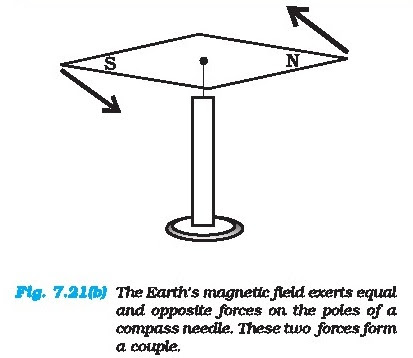
fingers are applying a couple to the lid [Fig. 7.21(a)]. Another known example
is a compaaa needle in the earth's magnetic field as
shown in the Fig. 7.21(h). The earth's magnetic
field exerts equal forces on the north and south poles. The force on the North
Pole is towards the north, and the force on the South Pole is toward the south.
Except when the needle points
in the north-south direction; the two forces do not
have the aame Hine of action. Thus there is a couple acting on the needle due
to the earth's magnetic field. ;

Example 7.7 Show that moment of a
couple does not depend on the point about which you
take the moments.
Anawer Consider a couple as shown in Fig. 7.22
acting on a rigid body. The forces F and -F act respectively at points B and A
These pointe have
posttion vectors r, and r, with respect to originO.
Let us take the moments of the forces about the origin.
The moment of the couple = sum of the
moments of the two forces making the couple
=2,x(-F)+4r,*F
=r,xF-9r,xF
= (r,-2,) x F
Butz, + AB =z,, and hence AB =r, -f,.
The moment of the couple, therefore, is
AB x F.Clearly this ts independent of the origin,
the point about which we took the moments of the forces. <
7.8.1 Principle of moments
An ideal lever ia essentially a light (i.e. of
negligible mass) rod pivoted at a point along ita length. This point is called
the fulcrum. A see-saw on the children’s playground is a typical
example of a lever. Two forces F, and F,, parallel
to each other and usually perpendicular to the lever, aa shown here, act on the
lever at distances d, and d, respectively from the fulcrum as shown in Fig.
7.23.
The lever is a system in mechanical
equilibrium. Let R be the reaction of the support at
the fulcrum; R is directed opposite to the forces F, and F,. For translational
equilibrium,
R-F,-F,=0 @
For considering rotational equilibrium we take the
moments about the fulcrum; the sum of moments must be zero,
GF, - 2,F,=0 (i Normally the anticlockwise
(clockwise)moments are taken to be positive (negative). Note
Racts at the fulcrum itself and has zero moment
about the fulcrum.
In the case of the lever force F, is usually some
weight to be lifted. It is called the load and its distance from the fulcrum d,
is called the load arm. Force F, is the effort applied to lift
the load; distance d, of the effort from the fulcrum
is the effort arm.
Eq. (i) can be written as
dF. =d,F, (7.32)
or load arm x load = effort arm x effort
The above equation expresses the principle of
moments for a lever. Incidentally the ratio F,/F,1s called the Mechanical
Advantage (M.A);
F_d,
MASE G (7.32b)
If the effort arm d, is larger than the load arm,
the mechanical advantage is greater than one. Mechanical advantage greater than
one means that a small effort can be used to lift a large load. There are
several examples of a lever
around you besides the see-saw. The beam ofa balance
is a lever. Try to find more such examples and identify the fulcrum, the effort
and effort arm, and the load and the load arm of the lever in each case.You may
easily show that the principle of moment holds even when the parallel forces
F,and F, are not perpendicular, but act at some angle, to the lever.
7.8.2 Centre of gravity
Many of you may have the experience of
balancing your notebook on the tip of a
finger.Figure 7.24 illustrates a similar experiment that you can easily
perform. Take an irregular-shaped cardboard and a narrow tipped object like a
pencil. You can locate by trial and error a point G on the cardboard where it
can be
balanced on the tip of the pencil. (The cardboard remains
horizontal in this position.) This point of balance is the centre of gravity
(CG) of the cardboard. The tip of the pencil provides a
vertically upward force due to which the
cardboard is in mechanical equilibrium. As shown in
the Fig, 7.24, the reaction of the tip is equal and opposite to Mg, the total
weight of (i.e., the force of gravity on) the cardboard and
hence the cardboard is in translational
equilibrium. It is also in rotational equilfbrium;
if it were not so, due to the unbalanced torque it would tilt and fall. There
are torques on the card board due to the forces of gravity like mg,mg .... etc,
acting on the individual particles that make up the cardboard.
The CG of the cardboard is so located that the total
torque on ft due to the forces mg, mg a. te. is Zero,
If r, is the position vector of the tth particte
ofan extended bady with respect to its CG, then the torque abont the CG, due to
the force of gravity on the particle is t,= 1, x mg. The total
gravitational torque about the CG fs zero, Le.
t= t= Nrxmg=0 (7.33)
We may thereiore, define the CG of a body as that
point where the total gravitational torque on the body is zero.
We notice that in Eq. (7.33), g is the same for all
particles, and hence it comes out of the summation. This gives, since g is
non-zero,¥ nx, =. Remember that the posttion vectors (r) are taken with respect
to the CG. Now, in
accordance with the reasoning given below Eq. (7.4a]
in Sec. 7.2, if the sum is zero, the origin must be the centre of mass of the
bedy.Thus, the centre of gravity of the body cotacides with the centre of mass
in uniform gravity or
gr

avity-free space. We note that this is true because the body being small, g does not
vary from one point of the body to the
other. If the body is ac extended that g varies from part to part of the body,
then the centre of gravity
and centre of maas will not coincide. Basically,the
two are different concepts. The centre of mass has nothing to do with gravity.
It depends only on the distribution of mass of the body.
In Sec. 7.2 we found out the position of the centre
of mass of several regular, homogeneous objects. Obviously the method used
there gives us also the centre of gravity of these bodies, if
they are small enough.
Figure 7.25 illustrates another way of
determining the CG of an regular shaped body like a
cardboard. If you suspend the body from some point like A, the vertical line
through A passea through the CG. We mark the vertical AA,. We then suapend the
body through other
points like B and C. The intersection of the
verticals gives the CG. Explain why the method works. Since the body is small
enough, the method allows us to determine also its centre of mass.
Example 7.8 A metal bar 70 cm long
and 4.00 kg in mass supported on two
knife-edgea placed 10 cm from each end.
A6.00 kg load is suspended at 30 cm from
one end. Find the reactions at the knife-edges.
(Assume the bar to be of untform crosa section and homogeneous.)
Answer Figure 7.26 shows the rod AB, the positions
of the knife edges K, and K, , the centre of gravity of the rod at G and the
suspended load at P.
Note the weight of the rod W acts at its
centre of gravity G. The rod is uniform in cross
section and homogeneous; hence G is at the centre of the rod; AB = 70 cm. AG =
35 cm, AP = 30 cm, PG = 5.cm, AK = BK, = 10 cm and K,G = KG = 25 cm. Also, W=
weight of the rod =4.00 kg and W,= suspended load = 6.00 kg;R, and R, are the
normal reactions of the support at the knife edges.
For translational equilibrium of the
rod,R,+R,-W,-W=0 0 Note W, and W act vertically down and R,and R, act
vertically up.
For considering rotational equilibrium, we take
moments of the forces. A convenient point to take moments about is G. The
moments of R, and W, are anticlockwise {+ve), whereas the
moment of R, {a clockwise (-ve).
For rotational equilibrium,
-R, (K,G) + W, (PG) + R, (K,G) = 0 (i
It ia given that W = 4.00g N and W, = 6.00g N, where
g = acceleration dune to gravity. We take g = 9.8 m/s’.With numerical values
inserted, from (i)
R,+ R, - 4.00g- 6.009 = 0
or R + K, = 10.00g N (iif)
= 98.00 N
From (ii), - 0.25 R, + 0.05 W, + 0.25 R,=0
or R, - R, = 1.2g N=11.76N (tv)
From (ft) and (iv), R, = 54.88 N,
R,=43.12N
Thus the reactions of the aupport are about 55 N at
K and 43 N at K.. <
Example 7.9 A 3m long ladder weighing
20 kg leans on a frictionless wall. Its feet rest on
the floor 1 m from the wall as shown in Fig.7.27. Find the reaction forces of
the wall and the floor.

The ladder AB is 3 m long, its foot A is at distance
AC = 1 m from the wall. From
Pythagoras theorem, BC = 2./2 m. The forces on the
ladder are its weight W acting at its centre of gravity D, reaction forces F,
and F, of the wall
and the floor respectively. Force F, is
perpendicular to the wall, since the wall is
frictionless. Force F, is resolved into two components, the normal reaction N
and the force of friction F: Note that F prevents the ladder from sliding away
from the wall and is therefore directed toward the wall.
For translational equilibrium, taking the forces in
the vertical direction,
N-W=0 (a)Taking the forces in the horizontal
direction,F-F,=0 (ii)
For rotational equilibrium, taking the
moments of the forces about A,
2f2 F, - (1/2) W=0 (ii
Now W= 20 g=20x9.8N= 196.0N
From () N= 196.0
From (if) F = W/4/2 = 196.0/4V2 =34.6N
From fi) F = F, =34.6N
F, =-¥F° 4+ N° =199.0N
The force F, makes an angle @ with the
horizontal,tan@=N/F=4J2, a@=tan(4¥2)=80
7.8 MOMENT OF INERTIA
We have already mentioned that we are
developing the study of rotational motion parallel
to the study of translational motion with which we are familiar. We have yet to
answer
one major question in this connection. What is the
analogue of mass in rotational motion?
We shall attempt to answer this question in the
present section. To keep the discussion simple,we shall consider rotation about
a fixed axis only. Let us try to get an expression for the
Kinetic energy of a rotating body. We know that for
a body rotating about a fixed axis, each particle of the body moves in a circle
with linear velocity given by Eq. (7.19). (Refer to Fig. 7.16).For a particle
at a distance from the axis, the linear velocity is v, = @. The kinetic energy
of motion of this particle is k =i my? ime
1 Qt ~” Q 0°
where m,is the masse of the particle. The total
kinetic energy K of the body is then given by the sum of the kinetic energies
of individual particles,
K=>k = 5 Lincie)
iol tel
Here nis the number of particles in the body.Note
ois the same for all particles. Hence, taking out of the sum,
Kate (Sime)
2 ‘fe
We define a new parameter characterising
the rigid body, called the moment of inertia J,given
by
I= > mr (7.34)
tel
With this definttion,
‘el ae
Kepler (7.35)
Note that the parameter J is independent of the
magnitude of the angular velocity. It is a characteristic of the rigid body and
the axis about which it rotates.
Compare Eq. (7.35) for the kinetic energy of a
rotating body with the expression for the kinetic energy of a body in linear
(translational)
motion,
K=imv
2
Here m is the mass of the body and uv is its
velocity. We have already noted the analogy between angular velocity «(in
respect ofrotational motion about a fixed axis) and linear velocity u (in
respect of linear motion). It is then evident that
the parameter, moment of inertia fF, is the desired rotational analogue of mass.
In rotation (about a
fixed axis), the moment of inertia plays a similar
Tole as mass does in inear motion.
We now apply the definition Eq. (7.34), to calculate
the moment of inertia in two simple cases.
(a) Consider a thin ring of radius R and mass M,
rotating in its own plane around its centre with angular velocity #. Each mass
element of the ring is at a distance R from the axis, and moves with a speed
Ra. The kinetic energy is therefore,Lo lage
Ke= 2 My = 2 MR‘ ar
Comparing with Eq. (7.35) we get I = MR?
for the ring.1

(b) Next, take a rigid massless rod of length ¢ with
a pair of small masses, rotating about an axis through the centre of mass
perpendicular to the rod (Fig. 7.28). Each mass M/2 is at a distance t/2 from
the axis.
The moment of inertia of the masses is
therefore given by
(M/2) (1/2)? + (M/2)(1/ 2)?
Thus, for the pair of masses, rotating about the
axis through the centre of mass perpendicular to the rod
I= MP/4 Table 7.1 gives the moment of inertia of
various familiar regular shaped solids about specific axes.
As the mass of a body resists a change in its atate
of linear motion, it is a meaaure of its inertia in linear motion. Similarly,
aa the moment of inertia about a given axis of rotation
resists a change in tte rotational motion, ft can be
regarded as a measure of rotational inertia of the body; it is a measure of the
way in which
different parts of the body are distributed at
different distances from the axis. Unlike the mass of a body, the moment of
inertia is not a fixed quantity but depends on the orientation
and position of the axis of rotation with respect to
the body as a whole. As a measure of the way in which the maas of a rotating
rigid body is distributed with respect to the axis of rotation,
we can define a new parameter, the radius of
gyration. It is related to the moment of inertia and the total mass of the
body.
Notice from the Table 7.1 that in all
cases, we can write I = Mk*, where k has
the dimension of length. For a rod, about the
perpendicular axis at its midpoint,i =V/l2.ie. k? =L/V12 . Similarly, k = R/2
for the circular disc about its diameter. The length iis a geometric property
of the body and
axis of rotation. It is called the radius of
@yration. The radius of gyration of a body about an axis may be defined as the
distance from the axia of a mass point whose masa is equa] to the mass of the
whole body and whose
moment of inertia is equal to the moment of inertia
of the body about the axis.
Thus, the moment of inertia of a rigid body depends
on the mass of the body, its shape and size; distribution of mass about the
axis of rotation, and the posttion and orientation of the
axis of rotation.
From the definition, Eq. {7.34), we can infer that
the dimensions of moments of inertia we ML? and its SI units are kg m?.
The property of this extremely important
quantity J as a measure of rotational inertia of the
body has been put to a great practical use.The machines, such as steam engine
and the automobile engine, etc., that produce rotational
motion have a disc with a large moment of inertia,
called a flywheel. Because of ita lange moment of inertia, the flywheel resists
the sudden increase or decrease of the speed of the vehicle. It allows a
gradual change in the speed
and prevents jerky motions, thereby ensuring asmooth
ride for the passengers on the vehicle.
7.10 THEOREMS OF PERPENDICULAR AND
PARALLEL AXES
These are two useful theorema relating to moment of
inertia. We shall first discuss the theorem of perpendicular axes and its
simple yet instructive application in working out the
moments of inertia of some regular-shaped bodies.

Theorem of perpendicular axes
This theorem is applicable to bodies which are
planar. In practice this means the theorem applies to flat bodies whose
thickness is very small compared to their other dimensions (e.g.length, breadth
or radius). Fig. 7.29 illustrates the theorem. It states that the moment of
inertia of a planar body (lavaina) about an axis perpendicular to its plane is
equal to the sam of its moments of inertia about two perpendicular axes
concurrent with
perpendicular axis and lying in the plane of the
body.
The figure showa a planar body. An axis
perpendicular to the body through a point O ts taken
as the z-axis. Two mutually perpendicular axes lying in the plane of the body
and concurrent with 2-axis, i.e. passing through O,are taken as the x and
y-axes. The theorem
states that Lal +l, (7.36)
Let us look at the usefulness of the theorem through
an example.
Example 7.10 What is the moment of
inertia of a disc about one ofits diameters?
Answer We aasume the moment of inertia of the disc
about an axis perpendicular to ft and through its centre to be known; it is MR
/2,where M is the mass of the diac and R is its tadtus (Table 7.1)
The disc can be considered to be a planar body.
Hence the theorem of perpendicular axes is applicable to it. As shown in Fig.
7.30, we take three concurrent axes through the centre
of the disc, O as the x,y,z axes; x and y-axes lie
in the plane of the disc and z is perpendicular to it. By the theorem of
perpendicular axes,Leal. +1,
Now, x and y axes are along two diameters of the
disc, and by symmetry the moment of inertia of the disc is the same about any
diameter. Hence
L=l,
and I= 21,
But i= MR/2
So finally, [,=1/2= MR/4
Thus the moment of inertia of a disc about any of
its diameter is MR°/4 . <
Find similarly the moment of inertia of a ring about
any ofits diameter. Will the theorem be applicable to a solid cylinder?

7.10.1 Theorem of parallel axes
This theorem is applicable to a body of any shape.
It allows to find the moment of inertia of a body about any ands, given the
moment of inertia of the body about a parallel axis through the centre of mass
of the body. We shall only
state this theorem and not give its proof. We shall,
however, apply it to a few simple situations which will be enough to convince
us about the
usefulness of the theorem. The theorem may be stated
as follows:
The moment of inertia of a body about any axis is
equal to the sum of the moment of inertia of the body about « parallel axis
passing through its centre of mass and the product of ite mass and the square
of the distance between the two parallel axes. As shown in the Mig. 7.31, z and
2 are two parallel axes separated by a distance a. The z-axis passes through the
centre of mass O of the rigid body.Then according to the theorem of parallel
axes L=h+M@ (7.37)
where J, and Fare the moments of inertia of the body
about the z and 2’ axes respectively, Mis the total mass of the body and ais
the perpendicular distance between the two parallel axes.
Example 7.11 What is the moment of
inertia of a rod of mass M, length l about an axis
perpendicular to it through one end?
Answer For the rod of mass M and length lt,I= MP/12.
Using the parallel axes theorem,P=! + Me with a=t/2 we get,
remen(s) aM 12 2 3
We can check this independently since I 1s half the
moment of inertia of a rod of mass 2M and length 21 about its midpoint,Peomteyi
MO 4
12 2 3
Example 7.12 What is the moment of
inertia of a ring about a tangent to the
circle of the ring?
Answer The tangent to the ring in the plane of the
ring is parallel to one of the diameters of the ring.
Example 7.13 Obtain Eq. (7.38) from first
principles.
Answer The angular acceleration is uniform,hence a =
a= constant {i)
Integrating this equation,a= Ja di+c
‘=at+c (as a is constant)
Att=0, w= a, (given)From (f we get at t= 0, m=c= am,
Thus, @ = ot + m, as required.
With the definition of = d8/dt we may
integrate Eq. (7.38) to get Eq. (7.39). This
derivation and the derivation of Eq. (7.40) is left as an exercise.
Example 7.14 The angular speed of a
motor wheel is increased from 1200 rpm
to 3120 rpm in 16 seconds. {i} What is its angular
acceleration, assuming the
acceleration to be uniform? (if) How many
revolutions does the engine make during this time?
Answer We shall use » = o,+ at , = initia] angular
speed in rad/s = 2n*x angular speed in rev/s ‘Qn x angular speed in rev/min =
60 s/min
‘2nx 1200 = —— rad/s
60
= 40% rad/s
Similarly @ = final angular speed in rad/s = 283120
rad/s
60
= 2nx 52 rad/s
= 104 rrad/s
“ Angular acceleration
a= Soh =4 rad/s?
The angular acceleration of the engine
= 4 rad/s?
(i The angular displacement in time t is
given by
@=a,t+ +a e
2
= (408x164+5x 4=x 16") rad
=(640#% +512") rad
= 11522 rad
Number of revolutions = ot 2576 4

7.12 KINEMATICS OF ROTATIONAL MOTION
ABOUT A FIXED AXIS
Table 7.2 lists quantities associated with linear
motion and their analogues in rotational motion.We have already compared
kinematics of the two motions. Also, we know that in rotational
motion moment of inertia and torque play the same
role as mass and force respectively in linear motion. Given this we should be
able to guess what the other analogues indicated in the
table are. For example, we know that in linear
motion, work done is given by F dx, in rotational motion about a fixed axis it
should be rg,since we already know the correspondence ‘dx > d@ and F +. It
is, however, necessary that these correspondences are established on
sound dynamical considerations. This is what Wwe now
turn to.
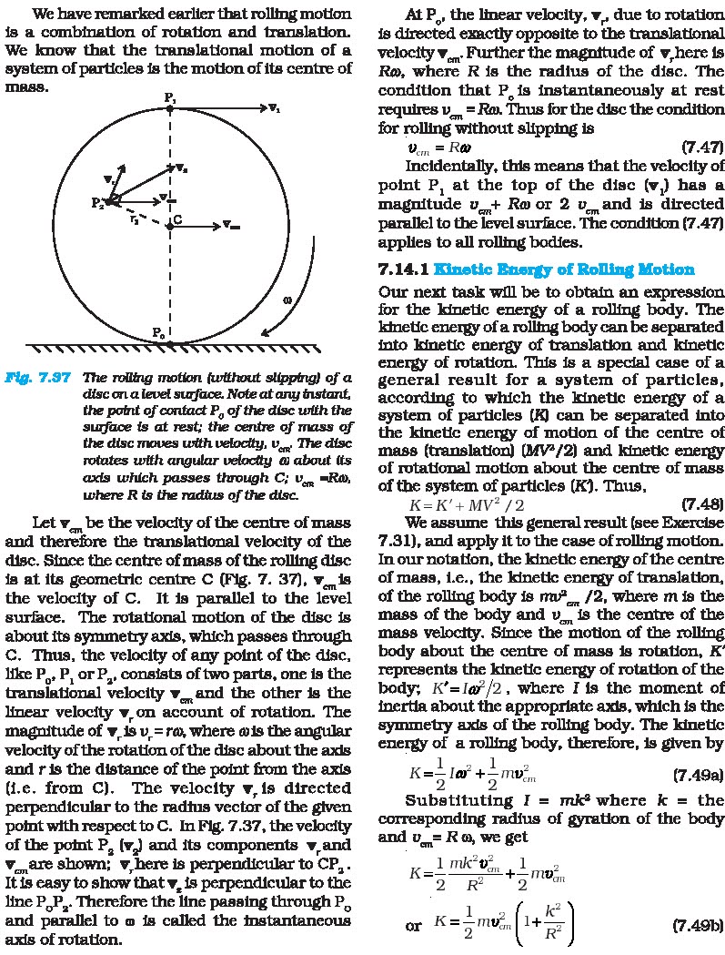
Before we begin, we note a simplification that arises in the case of
rotational motion about a fixed azis. Since the axis ts fixed, only those
components of torques, which are along
the direction of the fixed axis need to be
considered in our discussion. Only these components can cause the body to
rotate about the axis. A component of the torque perpendicular to the axis of
rotation will tend to turn the axis from its posttion. We specifically assume
that there will arise necessary forces of constraint to cancel the effect of
the perpendicular components of the (external)torques, so that the fixed
position of the axis will be maintained. The perpendicular components of the
torques, therefore need not be taken into account. This means that for our
calculation of torques on a rigid body:
(1) We need to consider only those forces that lie
in planes perpendicular to the axis.Forces which are paralle] to the axis will
give torques perpendicular to the axis and need not be taken into account.
(2) We need to consider only those components of the
position vectors which are perpendicular to the axis.Components of position
vectors along the axis will result in torques perpendicular to the axis and
need not be taken into account.

Figure 7.34 shows a cross-section ofa rigid body
rotating about a fixed axis, which is taken as the z-axis (perpendicular to the plane of the
page; see Fig. 7.33). As said above we need to
consider only those forces which lie in planes perpendicular to the axds. Let
F, be one such typical force acting as shown on a particle of the body at point
P, with ita line of action in a
Plane perpendicular to the axis. For convenience we
call this to be the x~y’ plane (coincident with the plane of the page). The
particle at P,describes a circular path of radius r, with centre
C on the axis; CP, =7F,.
In time Af, the point moves to the poattion P,’. The
displacement of the particle ds,,therefore, haa magnitude ds, = rd@ and
direction tangential at P, to the circular path as shown. Here d@ is the
angular displacement of the particle, d@= <P,CP, .The work done by
the force on the particle ts AW, =F,. ds,= F.ds,
cos¢,= F.(r, dQsina,where ¢, is the angle between F, and the tangent

at P, and @, is the angle between F, and the radius vector OP,; ¢, + &, = 90°.
The torque due to F, about the origin is
OP, x F,. Now OP, = OC + OP,. [Refer to
Fig. 7.17(b).] Since OC is along the axis, the
torque resulting from it is excluded from our consideration. The effective
torque due to F, is +,= CPx F ; it is directed along the axis of rotation and
has a magnitude ¢,= 7,F, sine , Therefore,dw, =7,de
If there are more than one forces acting on the
body, the work done by all of them can be added to give the total work done on
the body.Denoting the magnitudes of the torques due to the different forcea aa
¢,, f,, ... etc,
‘dW =(t, +t, +...)d@
Remember, the forces giving rise to the
torques act on different particles, but the angular
displacement d@ ia the same for all particlea. Since all the torques considered
are parallel to the fixed axia, the magnitude tof the total torque is just the
algebraic sum of the
magnitudes of the torques, 1e., t= 4+ 1, + .....We,
therefore, have ‘dW =1de (7.41)
This expression givea the work done by the total
(external) torque + which acts on the body rotating about a fixed axis. Ita
similarity with the corresponding expression dW=Fds
for linear (translational) motion is
obvious.Dividing both sides of Eq. (7.41) by dt gives
P ow _ oe _ TO)
dt dt
or P= (7.42)
This is the instantaneous power. Compare
this expression for power in the case of
rotational motion about a fixed axis with the
expression for power in the case of near motion,
P=Fu
Ina perfectly rigid body there is no internal
motion. The work done by external torques is therefore, not dissipated and goes
on to increase
the kinetic energy of the body. The rate at which
work is done on the body is given by Eq. (7.42).This is to be equated to the
rate at which kinetic
energy increases. The rate of increase of kinetic
energy is
(te) (20) deo
dt\ 2. 2 di
We assume that the moment of inertia does uot change
with time. This means that the mass of the body does not change, the body
remains rigid and also the axis does not change its position with respect to
the body.
Since a=dw/dt. we get
S[12 | 100
a2 |
Equating rates of work done and of increase in
kinetic energy,
‘To= loa wale (7.43)Eq. (7.43) is similar to
Newton's second law for Imear motion expressed symbolically as Fema
Just as force produces acceleration, torque produces
angular acceleration in a body. The angular acceleration is directly
proportional to the applied torque and is inversely proportional
to the moment of inertia of the body. Eq.(7.43)can
be called Newton's second law for rotation about a fixed axis.
Example 7.15 A cord of negligible mass
is wound round the rim of a fly wheel of
mass 20 kg and radius 20 cm. A steady
pull of 25 N is applied on the cord as shown in Fig.
7.35. The flywheel is mounted on a horizontal axle with frictionless bearings.
(a) Compute the angular acceleration of
the wheel.
(b) Find the work done by the pull, when
2m of the cord is unwound.
(c) Find also the kinetic energy of the
whee] at this point. Assume that the
whee] starts from rest.
(d) Compare answers to parts (b) and (c).

(a) We use
Ia@=f
the torque t=FR
=25 X 0.20 Nm (as R=0.20m)
= 5.0 Nm
I=M. 1. of flywheel about its axia SS
20.0x(02) = 0.4 kg m*
@= angular acceleration
= 5.0 N m/0.4 kg m? = 12.5 s*
(b) Work done by the pull unwinding 2m of the cord
=25NX2m=50J
(c) Let @ be the final angular velocity. The 1 2
kinetic energy gained = 3 @.since the wheel starts from rest. Now,of =@ +200,
a,=0 The angular displacement 6 = length of unwound string / radius of wheel =
2m/0.2 m = 10 rad @ =2x12.5x10.0 = 250(rad/s)?. KE. gained = = x 0.4 x 250 =
50J (d) The answers are the same, Le. the kinetic energy gained by the wheel =
work done by the force. There is no loss of energy due to friction.
7.13 ANGULAR MOMENTUM IN CASE OF ROTATION
ABOUT A FIXED AXIS
We have studied in section 7.7, the angular momentum
ofa system of particles. We already know from there that the time rate of total
angular momentum of a system of particles about a point is equal to the total
external torque on the system taken about the same point.When the total
external torque is zero, the total angular momentum of the system is conserved.
We now wish to study the angular momentum in the
special case of rotation about a@ fixed axis. The general expression for the
total angular momentum of the system is
N
L= 1 Xp, (7.25)
iol
We firat consider the angular momentum of a typical
particle of the rotating rigid body. We then sum up the contributions of
individual particles to get L of the whole body.For a typical particle 1 = r x
p. As seen in the last section r = OP = OC + CP [Fig. 7.17(b)].
With p=mv,1=(0C x mv) + (CPx mv)
The magnitude of the linear velocity w of the
particle at P is given by v = wr, where r, is the length of CP or the
perpendicular distance of P from the axis of rotation. Further, v is tangential
at P to the circle which the particle describes.Using the right-hand rule one
can check that CP x v is parallel to the fixed axis. The unit
vector along the fixed axis (chosen as the 2-axis)is
, . Hence CP xmve=r, (mv) k = mrok (since v=ur,)
Similarly, we can check that OC x vw is
perpendicular to the fixed axis. Let us denote the
part of 1 along the fixed axis {1.e. the z-axis)by L, then
‘L, = CPx mv = mrok and 1=1,+O0Cxmv
We note that I, is parallel to the fixed axts,but
lis not. In general, for a particle, the angular momentum 1 is not along the
axis of rotation,i.e. for a particle, 1 and o are not necessarily
paralle]. Compare this with the corresponding fact
in translation. For a particle, p and v are always parallel to each other.
For computing the total angular momentum
of the whole rigid body, we add up the
contribution of each particle of the body.Thus
L=31=)1,+ 0c, xmvy,We denote by L_ and L, the components of L respectively
perpendicular to the z-axis and along the z-axis;L, => 0€, x my, {7.44a)
where m, and v, are respectively the mass and the
velocity of the f particle and C, is the centre of the circle described by the
particle;and L,-D1.-[E mat oR or L, = lok (7.44b)
The last step follows since the perpendicular
distance of the f particle from the axia 1s 1;and by definttion the moment of
inertia of the body about the axis of rotation is [= mr? .
Note L=L, + L_ (7.44c)
The rigid bodiea which we have mainly
considered in this chapter are symmetric about the
axis of rotation, i.c. the axis of rotation is one of their symmetry axea. For
such bodies,for a given OC, for every particle which haa a velocity v, , there
is another particle of velocity -¥, located diametrically opposite on the
circle with centre C, described by the particle. Together such pairs will
contribute zero to L_ and asa
result for symmetric bodies L_ is zero, and hence
L=L, = lok (7.44)
For bodies, which are not symmetric about the axis
of rotation, L is not equal to L, and hence L does not lie along the axis of
rotation.
Referring to table 7.1, can you tell in which cases
L = L, will not apply?
Let us differentiate Eq. (7.44b). Since { isa fixed
(constant) vector, we get
d id =
S(t, )-|2(10) i
Now, Eq. (7.28b) states
‘aL -
di
As we have seen in the last section, only those
components of the external torques which are along the axis of rotation, need
to be taken into account, when we discuss rotation about a
fixed axis. This means we can take 1+ = tk.Since L
=L, + L, and the direction of L, (vector ‘i¢) 18 fixed, it follows that for
rotation about a fixed axia,
‘dL, os
a {7.45a)
‘dL
and “a9 (7.45b)
Thus, for rotation about a fixed axis, the component
of angular momentum
perpendicular to the fixed axis is constant. As L, =
lok , we get from Eq. (7.45a),<(10)=1 (7.450)
If the moment of inertia I does not change with
time,d, do
di (l@)=I di: la
and we get from Eq. (7.45c),
‘t=la (7.43)
We have already derived this equation using the work
- kinetic energy route.
7.13.1 Conservation of angular momentum
We are now in a position to revisit the principle of
conservation of angular momentum in the context of rotation about a fixed axis.
From Eq.(7.45c), if the external torque is zero,
L, = Jo = constant (7.46)
For symmetric bodies, from Eq. (7.44d}, L, may be
replaced by L (Land L, are respectively the magnitudes of L and L..)
This then is the required form, for fixed axis
rotation, of Eq. (7.29a), which expreases the general law of conservation of
angular momentum of a system of particles. Eq. (7.46)
applies to many situations that we come across in
daily life. You may do this experiment with your friend. Sit on a swivel chair
with your arms folded and feet not resting on, f.e., away
from, the ground. Ask your friend to rotate the
chair rapidly. While the chair is rotating with considerable angular speed
stretch your arms

horizontally. What happens? Your angular
speed is reduced. If you bring back your arms closer
to your body, the angular speed increases again. This is a situation where the
principle of conservation of angular momentum is
applicable. If friction in the rotational mechanism
is neglected, there is no external torque about the axis of rotation of the
chair and hence Iais constant. Stretching the arms increases I about the axis
of rotation, resulting
in decreasing the angular speed Bringing the arms
closer to the body has the opposite effect.
Acircus acrobat and a diver take advantage of this
principle. Also, skaters and classical,Indian or western, dancers performing a
pirouette on the toes of one foot display ‘mastery’
over this principle. Can you explain?
7.14 ROLLING MOTION
One of the most common motions observed in daily
life is the rolling motion. All wheels used in transportation have rolling
motion. For specificness we shall begin with the case of a
disc, but the result will apply to any rolling body
rolling on a level surface. We shall assume that the disc rolls without
slipping. This means that
at any instant of time the bottom of the disc which
is in contact with the surface is at rest on the surface.
We have remarked earlier that rolling motion is a combination of rotation and translation.We know that the translational motion of a system of particles is the motion of its centre of mass.

Let v,, be the velocity of the centre of mass
and therefore the translational velocity of the
disc. Since the centre of mass of the rolling disc
ia at ite geometric centre C (Fig. 7. 37), v,,,18 the velocity of C. It is
parallel to the level
surface. The rotational motion of the disc is about
its symmetry axis, which passes through Cc. Thus, the velocity of any point of
the diac,like P,, P, or P,, consists of two parts, one is the
translational velocity v_ and the other is the
linear velocity v.on account of rotation. The magnitude of v_is v_=re, where
wis the angular velocity of the rotation of the disc about the axis
and ris the distance of the point from the axis
(i.e. from C). The velocity v,is directed perpendicular to the radius vector of
the given point with respect to C. In Fig. 7.37, the velocity
of the point P, (v,) and its components v,and v,,are
shown; v,here is perpendicular to CP,.It is easy to show that v, is
perpendicular to the
line P,P... Therefore the line passing through P,,
and parallel to o is called the instantaneous axis of rotation.
At P,, the linear velocity, v,, due to rotation is
directed exactly opposite to the translational velocity v,,,. Further the
magnitude of v,here is Ro, where R is the radius of the disc. The
condition that P,is instantaneously at rest requires
v= Res, Thus for the disc the condition for rolling without slipping is 0, = Re
(7.47)
Incidentally, this means that the velocity of point
P, at the top of the disc (v,) has a magnitude v_+ Rw or 2 v_,and is directed
parallel to the level surface. The condition (7.47)applies to all rolling bodies.
7.14.1 Kinetic Energy of Rolling Motion
Our next task will be to obtain an expression for
the kinetic energy of a rolling body. The kinetic energy of a rolling body can
be separated
into kinetic energy of translation and kinetic
energy of rotation. This is a special case of a general result for a system of
particles,according to which the kinetic energy of a system of particles (KX)
can be separated into
the kinetic energy of motion of the centre of mnass
(translation) (MfV7/2) and kinetic energy of rotational motion about the centre
of mass of the system of particles (K). Thus,K=K'+ MV? /2 (7.48)
We assume this general result (see Exercise 7.31),
and apply it to the case of rolling motion.In our notation, the kinetic energy
of the centre of mass, i.e., the kinetic energy of translation,of the rolling body is mv*_ /2,
where m is the mass of the body and v_, is the centre of the mnass velocity.
Since the motion of the rolling body about the centre of mass is rotation,
K’represents the kinetic energy of rotation of the body; K’=I@/2, where I is
the moment of inertia about the appropriate axis, which is the symmetry axis of
the rolling body. The kinetic energy of a rolling body, therefore, is given by
K =5 lox +5iwi, (7.49a)
Substituting I = mk® where k = the
corresponding radius of gyration of the body and v_
= Ra, we get Kak etn yd mei,
2 RF 2
1 sos ke
or K= 2 MUG, ( Py ) (7.49b)
Equation (7.49b) applies to any rolling body:a disc,
a cylinder, a ring or a sphere.
Example 7.16 Three bodies, a ring, a solid cylinder
and a solid sphere roll down the sarge incHned plane without sipping. They
start from rest. The radii of the bodies are identical. Which of the bodies
reaches the ground with maxbuum velocity?
Answer We assume conservation of energy of the
rolling body, Le. there is no loss of energy due to friction etc. The potential
energy lost by the body in rolling down the inclined plane
(= mgh) must, therefore, be equal to kinetic energy
gained. (See Fig.7.38) Since the bodies start from rest the kinetic energy
gained is equal to the final kinetic energy of the bodies. From
1 2 ke Eq, (7.49), Kap mv (+f). where v is the final
velocity of (the centre of mass of the body.Equating K and mgh,

mgh <1 ny? Ga
2 R
3 2gh
vy =| —
or (re |
Note is independent of the mass of the
rolling body;
For a ring, k° =
Dany = 2ah
. {ist .
= Jon
For a solid cylinder kK? = F°/2
_ | 2gh
Pew | 141/2
_ 4gh
7 { 3
For a solid sphere i* = 2R°/5
_ 2gh
Dophere com 14+2/5
_ 10gh
7 1 7
From the results obtained itis clear that among the
three bodies the sphere has the greatest and the ring has the least velocity of
the centre of mass
at the bottom of the inclined plane.
Suppose the bodies have the same mass. Which body
has the greatest rotational Ininetic enexgy while reaching the bottem of the
inclined plane? 4
SUMMARY
1. Ideally, a rigid body is one for which the
distances between different particles of the body do not change, even though
there are forces on them.
2. Arigid body fixed at one point or along a line
can have only rotational motion. A rigid body not fixed in some way can have
efther pure translation or a combination of translation and rotation.
3. In rotation about a fixed axis, every particle of
the rigid body moves in a circle which Hes in a plane perpendicular to the axis and has ite centre
on the axis. Every Point in
the rotating rigid body has the same angular
velocity at any instant of time.
4. In pure translation, every particle of the body
moves with the same velocity at any instant of time.
5. Angular velocity is a vector. Ite magnitude ie @
= d0/dt and it fa directed along the axle of rotation. For rotation about a
fixed axis, this vector has a fixed direction.
6. The vector or cross product of two vector a and b
is a vector written as a x b. The magnitude of this vector ie absind and ite
direction is given by the right handed screw or the right hand rule.
7. The linear velocity of a particle of a rigid body
rotating about a fixed axis is given by v=o fF, where £ is the position vector
of the particle with respect to an origin along the fixed axis. The relation
applies even to more general rotation of a rigid body with one point fixed. In
that case r is the position vector of the particle with respect to the fixed
point taken as the origin.
8. The centre of mase of a system of particles is
defined as the point whose position vector is
9. Velocity of the centre of mass of a ayatem of
particles is given by V= P/M, where F is the linear momentum of the system. The
centre of mass moves as if all the mass of the system is concentrated at this
point and all the external forces act at it. If the total
external force on the system is zero, then the total
linear momentum of the system is constant.
10. The angular momentum of a system of n particles
about the origin is
L = ¥nxp,
t2l
The torque or moment of force on a system of n
particles about the origin is
t=) 1xF,
1
The force F, acting on the ¢@ particle includes the
external as well as internal forces.Assuming Newton's third law and that forces
between any two particles act along the line joining the particles, we can show
1,, = 0 and
a
11. A rigid body is in mechanical equilibrium if
(1) itis in tranalational equilibrium, Le., the
total external force on it is zero : SF=0,and
(2) it ie in rotational equilibrium, 1.e. the total
external torque on it ia zero :¥a= ¥nxk=0.
12. The centre of gravity of an extended body is
that point where the total gravitational torque on the body is zero.
13. The moment of intertia of a rigid body about an
axis is defined by the formula lem where 7, is the perpendicular distance of the th point of the
body from the axis. The ol ye
kinetic energy of rotation ie Kes le,
14. The theorem of parallel axes: ‘el, +Ma?, allows
us to determine the moment of intertia of a rigid body about an axis as the sum
of the moment of inertia of the body about a parallel axis through its centre
of masse and the product of masse and square of the perpendicular distance
between these two axes.
15. Rotation about a fixed axis is directly
analogous to linear motion in respect of kinematics and dynamics.
16. For a rigid bedy rotating about a fixed axis
(say, z-axis) of rotation, L, = Im, where lis the moment of inertia about
z-axis. In general, the angular momentum L for such a body is not along the
axis of rotation. Only if the bedy is symmetric about the axis of rotation, L
is along the axis of rotation. In that case, |L|= L, = Iw. The angular
acceleration of a rigid body rotating about a fixed
axia ia gtven by Ig = +. If the external torque 7 acting on the body is zero,
the component of angular momentum about the fixed axis (say, 2-axia), L, (=a)
of such a rotating body is constant.
17. For rolling motion without alipping v_, = Re,
where v_, is the velocity of translation (1.e.of the centre of maas), Ris the
radtus and mia the mass of the body. The kinetic energy of such a rolling body
is the aum of kinetic energies of translation and rotation:
K=im 2, +102,
2 2

POINTS TO PONDER
1. To determine the motion of the centre of masa of
a system no knowledge of internal forces of the system ig required. For thia
purpose we need to know only the external forcea on the body.
2. Separating the motion of a system of particles as
the motion of the centre of mass, f1.c.,the tranalational motion of the aystem)
and motion about {i.e relative to) the centre of masa of the system ja a useful
technique m dynamics of a system of particles. One example of thia technique is
separating the kinetic energy of a system of particles K as
the kinetic energy of the system about its centre of
mass K’ and the kinetic energy of the centre of mass MV?/2,
K= K’+ MV7/2
3. Newton's Second Law for finite alized bodies (or
syatems of particles} ia based in Newton's Second Law and also Newton's Third
Law for particles.
4. To establish that the time rate of change of the
total angular momentum of a system of particles is the tota) external torque in
the syatem, we need not only Newton's second law for particles, but also
Newton's third law with the proviaton that the forcea between.any two particlea
act along the Hne joining the particles.
5. The vanishing of the total external force and the
vanishing of the total external torque are independent conditiona. We can have
one without the other. In a couple, total external force is zero, but total
torque is non-zero.
6. The total torque on a syatem is Mdependent of the
origin tf the total external force is zero.
7. The centre of gravity of a body coincides with
its centre of maas only if the gravitational field does not vary from one part
of the body to the other.
8. The angular momentum L and the angular velocity
are not necessarily parallel vectors.However, for the simpler situations
discussed in this chapter when rotation ia about a
fixed axis which is an axis of aymmetry of the rigid
body, the relation L = ia holds good,where I is the moment of the inertia of
the body about the rotation axis.
EXERCISES
7.1 Gave the location of the centre of masse of a
{i) sphere, (ii) cylinder, (iii) ring, and {iv)cube, cach of uniform mass
density. Does the centre of mass of a body necessarily lie inside the bedy ?
7.2 In the HC1 molecule, the separation between the
nucle of the two atoms is about
1.27 A(1 A= 10-10 ny. Find the approximate location
of the CM of the molecule,given that a chlorine atom is about 35.5 times as
massive as a hydrogen atom and nearly all the mass of an atom is concentrated
in its nucleus.
7.3 Achild alte stationary at one end of a long
trolley moving uniformly with a speed V on a emooth horizontal floor. If the
child gete up and rune about on the trolley in any manner, what ia the speed of
the CM of the (trolley + child) system ?
7.4 Show that the area of the triangle contained
between the vectors a and b is one half of the magnitude of a x b.
7.6 Show that a-(b x c) is equal in magnitude to the
volume of the parallelepiped formed on the three vectors , a, b and c.
7.6 Find the components along the x, y, z axca of
the angular momentum IJ of a particle,whose position vector is r with components
x, y, z and momentum ia p with components p,, p, and p,, Show that if the
particle moves only in the x-y plane the angular momentum has only a
z-component.
7.7 Two particles, cach of mass mand speed v, travel
in opposite directions along parallel lines separated by a distance d. Show
that the vector angular momentum of the two particle system is the same
whatever be the point about which the angular momentum ie taken.
7.8A non-uniform bar of weight W is suspended at
rest by two strings of negligible weight as shown in Fig.7.390. The angles made
by the strings with the vertical are 36.9° and 53.1°respectively. The bar is 2
m long. Calculate the distance d of the
centre of gravity of the bar from ite left end.

7.9 Acar weighs 1800 kg. The distance between its
front and back axics is 1.8 m. Its centre of gravity is 1.05 m behind the front
axle. Determine the force exerted by the level ground on each front wheel and
each back wheel.
7.10 Find the moment of inertia of a sphere about a
tangent to the sphere, given the moment of inertia of the sphere about any of
its diameters to be 2MR®°/5, where M is the masse of the sphere and R is the
radius of the sphere.
(b) Given the moment of inertia of a disc of mass M
and radius R about any of its diameters to be MF°/4, find its moment of inertia
about an axis normal to the disc and passing through a point on ite edge.
7.11 Torques of equal magnitude are applied to a
hollow cylinder and a solid sphere, both having the same mass and radtus. The
cylinder is free to rotate about its standard axie of symmetry, and the sphere
is free to rotate about an axis passing through its centre. Which of the two
will acquire a greater angular speed after a given time.
7.12 Aaolid cylinder of mass 20 kg rotates about its
axis with angular speed 100 rad "1.The radiue of the cylinder is 0.25 m.
What ia the kinetic energy associated with the rotation of the cylinder? What
fa the magnitude of angular momentum of the cylinder
about ita axis?
7.13 (a) A child stands at the centre of a turntable
with his two arms outstretched. The turntable ts set rotating with an angular
speed of 40 rev/min. How much is the angular speed of the child if he folds his
hands back and thereby reduces his moment of inertia to 2/5 times the initial
value ? Assume that the turntable rotates without friction.
(b) Show that the child’s new kinetic energy of
rotation is more than the mitial Kinetic energy of rotation. How do you account
for this increase in kinetic energy?
7.14 Arope of negligible mass is wound round a
hollow cylinder of mass 3 kg and radius 40 cn. What ia the angular acceleration
of the cylinder if the rope ie pulled with a force of SO N ? What is the linear
acceleration of the rope ? Assume that there ia no slipping.
7.18 To maintain a rotor at 2 uniform angular speed
of 200 rad s”!, an engine needs to transmit a torque of 180 N m. What is the
power required by the engine ?
(Note: uniform angular velocity in the absence of
friction implies zero torque. In practice, applied torque is needed to counter
frictional torque). Assume that the engine is 100% efficient.
7.18 From a uniform disk of radius R, a circular
hole of radius R/2 is cut out. The centre of the hole is at R/2 from the centre
of the original disc. Locate the centre of gravity of the resulting fat body.
7.17 Armetre stick is balanced on a knife edge at
ita centre. When two coins, each of mass 5 g are put one on top of the other at
the 12.0 cm mark, the stick is found to be balanced at 45.0 cm. What is the
mass of the metre stick?
7.18 A solid sphere rolls down two different
inclined planes of the same heights but different angles of inclination. (a)
Will it reach the bottom with the same speed in each case? (b) Will it take
longer to roll down one plane than the other? (c) If so,
which one and why?
7.18 Ahoop of radius 2 m weighe 100 kg. It rolle
along a horizontal floor so that its centre of mass has a speed of 20 cmn/e.
How much work has to be done to atop it?
7.20 The oxygen molecule has a mass of 5.30 x 10” kg
and a moment of inertia of
1.94x10 kg m? about an axis through ite centre
perpendicular to the lines joining the two atoms. Suppose the mean speed of
such a molecule in a gas is 500 m/s and that its kinetic energy of rotation is
two thirds of its kinetic energy of translation.Find the average angular
velocity of the molecule.
7.21 A solid cylinder rolls up an inclined plane of
angle of inclination 30°. At the bottom of the inclined plane the centre of
mass of the cylinder has a speed of 5 m/s.
(a) How far will the cylinder go up the plane?
(b) How long will it take to return to the bottom?
Additional Exercises
7.22 As ehown in Fig.7.40, the two sides of a step
ladder BA and CA are 1.6 m long and hinged at A. Arope DE, 0.5 m is ted half
way up. A weight 40 kg is suspended from a point F, 1.2 m from B along the
ladder BA. Assuming the floor to be frictionless and neglecting the weight of
the ladder. find the tension in the rope and forces exerted by the floor on the
ladder. (Take g = 9.8 m/s4)
(Hint: Consider the equilibrium of each side of the
ladder separately.)

7.23 A man stands on a rotating platform, with his
arme stretched horizontally holding a 5 kg weight in each hand. The angular
speed of the platform is 30 revolutions per minute. The man then brings his
arms close to his body with the distance of each weight from the axis changing
from 90cm to 20cm. The moment of inertia of the man together with the platform
may be taken to be constant and equal to 7.6 kg m*.
(a} What ie his new angular speed? (Neglect
friction.)
(b) Ie kinetic energy conserved in the process? If
not, from where does the change come about?
7.24 A bullet of masse 10 g and speed 500 m/s is
fired into a door and gets embedded exactly at the centre of the door. The door
is 1.0 m wide and weighs 12 kg. It is hinged at one end and rotates about a
vertical axis practically without
friction. Find
the angular speed of the door just after the bullet
ambeds inte it.
(Hint: The moment of inertia of the door about the
vertical axis at one end is ML?/3.}
7.25 Two disce of moments of inertia J) and Ip about
their respective axes (normal to the diec and passing through the centre), and
rotating with angular speeds a) and «2 are brought into contact face to face
with their axes of rotation coincident. (a) What
is the angular speed of the two-disc system? (b)
Show that the kinetic energy of the combined system is less than the sum of the
initial kinetic energies of the two discs.How do you account for this loss in
energy? Take 0] # @32.
7.26 (a} Prove the theorem of perpendicular axes.
(Hint : Square of the distance of a point (x, y) in
the x-y plane from an axis through the origin and perpendicular to the plane is
17+y3.
(b) Prove the theorem of parallel axes.
(Hint : If the centre of masa is chosen to be the
origin ) 1,1, = 0),
7.27 Prove the result that the velocity vu of
translation of a rolling body {like a ring, disc,cylinder or sphere) at the
bottom of an inclined plane of a height h is given by 2 2gh w= oF
(14k? /R*)using dynamical consideration (i.c. by consideration
of forces and torques). Note kis the radius of gyration of the body about ite
symmetry axis, and R is the radius of the body. The body starts from rest at
the top of the plane.
7.28 A disc rotating about ite axis with angular
speed @p is placed lightly (without any tranalational push) on a perfectly
frictionless table. The radius of the disc is R. What are the lincar velocities
of the pointa A, B and C on the disc shown in Fig. 7.41? Will the disc roll in
the direction indicated ?

7.29 Explain why friction is necessary to make the
disc in Fig. 7.41 roll in the direction indicated.
(a) Give the direction of frictional force at B, and
the sense of frictional torque, before perfect rolling
begins.
(b) What is the force of friction after perfect
rolling begins ?
7.30 Asolid disc and a ring, both of radius 10 cm
are placed on a horizontal table simultanecualy, with mitial angular speed
equal to 10 1 rad 6-1. Which of the two will start to roll
earlier ? The co-efficient of kinetic friction ia as
0.2.
7.31 Acylinder of mass 10 kg and radius 15 om ia
rolling perfectly on a plane of inclmation 30°. The co-efficient of static
friction fj, = 0.25.
(a) How much is the force of friction acting on the
cylinder ?
(b) What is the work done against friction during
rolling ?
(c) If the inclination of the plane is increased, at
what value of does the cylinder begin to skid,and not roll perfectly ?
7.32 Read each statement below carefully, and state,
with reasons, ff ft is true or false;
(a) Durmg rolling, the force of friction acts in the
same direction as the direction of motion of the CM of the body.
(b) The instantaneous speed of the point of contact
during rolling is zero.
(c) The instantaneous acceleration of the point of
contact during rolling is zero.
(d) For perfect rolling motion, work done against
friction is zero.'
(e) A wheel moving down a perfectly frictionless
inclmed plane will undergo slipping (not rolling)motion.
7.33 Separation of Motion of a system of particles
into motion of the centre of mass and motion about the centre of mass :( Show
p=p’ +m,V where p,is the momentum of the ith particle (of mass m) and p’,=
m,v’, Note v’, is the velocity of the ith particle relative to the centre of
mass.Also, prove using the definition of the centre of mass > p =0
(b) Show K = K’+'42MV" where K is the total
kinetic energy of the syatem of particles, ;<‘ is the total kinetic energy
of the system when the particle velocities are taken with respect to the centre
of mass and MV*/2 is the kinetic energy of the translation of the system as a
whole {i.c. of the centre of masse motion of the system). The result has been
used in Sec. 7.14.
(c) Show L=L’+ Rx MV
where [’= ) 1’ X pi is the angular momentum of the
system about the centre of mase with velocitics taken relative to the centre of
mass. Remember r’=r, -R; reat of the notation is the standard notation used in
the chapter. Note |’ and MRxV can be said to be angular momenta, respectively,
about and of the centre of mass of the system of
particles.
(a) Show a te Further, show that
a’ a Vert where 7, is the sum of all external
torques acting on the system about the centre of mase.(Hint : Use the
definition of centre of mass and Newton's Third Law. Assume the internal forces
between any two particles act along the line joining the particles.)
Pluto - A Dwarf Planet
The International Astronomical Union ([AU) at the
IAU 2006 General Assembly
held on August 24, 2006, in Prague in Czech
Republic, adopted a new definition of planets in our Solar System.According to
the new definition,Pluto is no longer a planet. This means that the Solar
System consists of eight planets: Mercury, Venus, Earth, Mars, Jupiter, Saturn,
Uranus and Neptune. According to the [AU usage, the ‘planet’ and ‘other bodies’
in our Solar System, except satellites, are to be defined into three
distinct categories of celestial objects
in the following way:
1. A ‘planet’ is a celestial body that {a) is in
orbit around the Sun, (b) has
sufficient mass for its self- gravity to overcome rigid
body forces so that it
assumes a hydrostatic equilibrium (nearly round)
shape, and (c) has
cleared the neighbourhood around its orbit.
2. A ‘dwarf planet’ is a celestial body that (a) is
in orbit around the Sun,
(b) has sufficient mass for its self- gravity to
overcome rigid body forces so
that it assumes a hydrostatic equilibrium (nearly
round) shape, (c} has not cleared the neighbourhood around its orbit, and {d)
is not a satellite.
3. All ‘other objects’, except satellites, orbiting
the Sun, shall be referred to collectively as ‘Small Solar-System Bodies’.
Unlike other eight planets in the Solar System,
Pluto's orbital path overlaps
with ‘other objects’ and the planet Neptune. The
‘other objects’ currently
include most of the Solar System asteroids, most of
the Trans-Neptunian
Objects (TNOs), comets, and other small bodies.Pluto
is a ‘dwarf planet’ by the above definition and is recognised as the prototype
of a new category of Trans-Neptunian Objects.